
How Does an RECD Kit Work? Complete Working Principle of DOC, DPF and Diesel Generator Emission Control
Diesel generator sets are essential for backup and industrial power generation. However, diesel combustion also produces harmful exhaust pollutants, including Particulate Matter (PM), Carbon Monoxide (CO) and unburnt Hydrocarbons (HC).
A Retrofit Emission Control Device (RECD) is an exhaust after-treatment system designed to reduce selected pollutants from existing diesel generators without replacing the entire DG set.
JBDS Power, an RECD Kit Manufacturer in India, develops advanced emission-control solutions using Diesel Oxidation Catalyst (DOC) and Diesel Particulate Filter (DPF) technology.
This technical guide explains the complete RECD working mechanism, from the moment untreated exhaust leaves the diesel engine until the treated exhaust exits the system. It also explains catalytic chemical reactions, soot filtration, regeneration, exhaust temperature and back-pressure management.
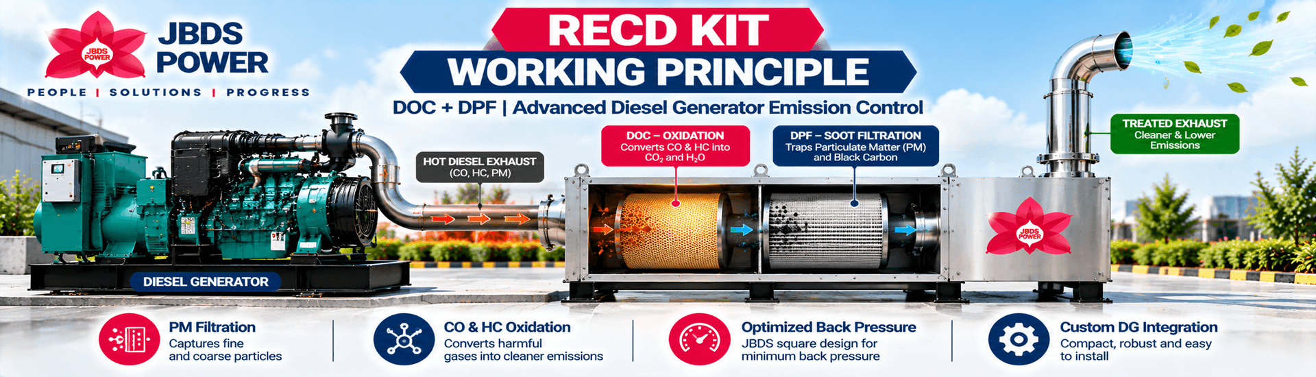
Complete RECD Process:
Diesel Engine → Exhaust Inlet → DOC Oxidation → DPF Filtration → Soot Management → Treated Exhaust → Outlet Stack
The performance of each stage depends on system design, DG loading, exhaust temperature, maintenance condition and engine characteristics.
What Is an RECD Kit and Why Is It Installed on a DG Set?
An RECD (Retrofit Emission Control Device) is a specialized pollution-control device installed in the exhaust system of an existing diesel generator.
Instead of changing the engine's original combustion mechanism, the RECD treats pollutants after combustion, before exhaust gases are discharged into the atmosphere.
Major objectives of an RECD
Reduce particulate matter and diesel soot emissions.
Reduce carbon monoxide and certain unburnt hydrocarbons.
Improve the emissions performance of existing diesel generators.
Support compliance with applicable pollution-control requirements.
Retain existing power-generation equipment where technically suitable.
Pollutants generated by diesel combustion
Pollutant | How it is produced | RECD treatment |
|---|---|---|
Particulate Matter (PM) | Incomplete combustion and soot formation | DPF filtration |
Carbon Monoxide (CO) | Incomplete oxidation of fuel | DOC catalytic oxidation |
Hydrocarbons (HC) | Unburnt or partially burnt fuel | DOC catalytic oxidation |
Visible black smoke | Soot-rich exhaust | DPF soot capture |
Nitrogen Oxides (NOx) | High-temperature combustion chemistry | Not substantially controlled by a conventional DOC + DPF alone |
Important: A DOC + DPF-based RECD is primarily intended to treat PM, CO and HC. It should not be presented as a complete NOx-removal system unless the particular configuration includes additional proven NOx-control technology.
Complete Working Mechanism of a JBDS Power RECD Kit
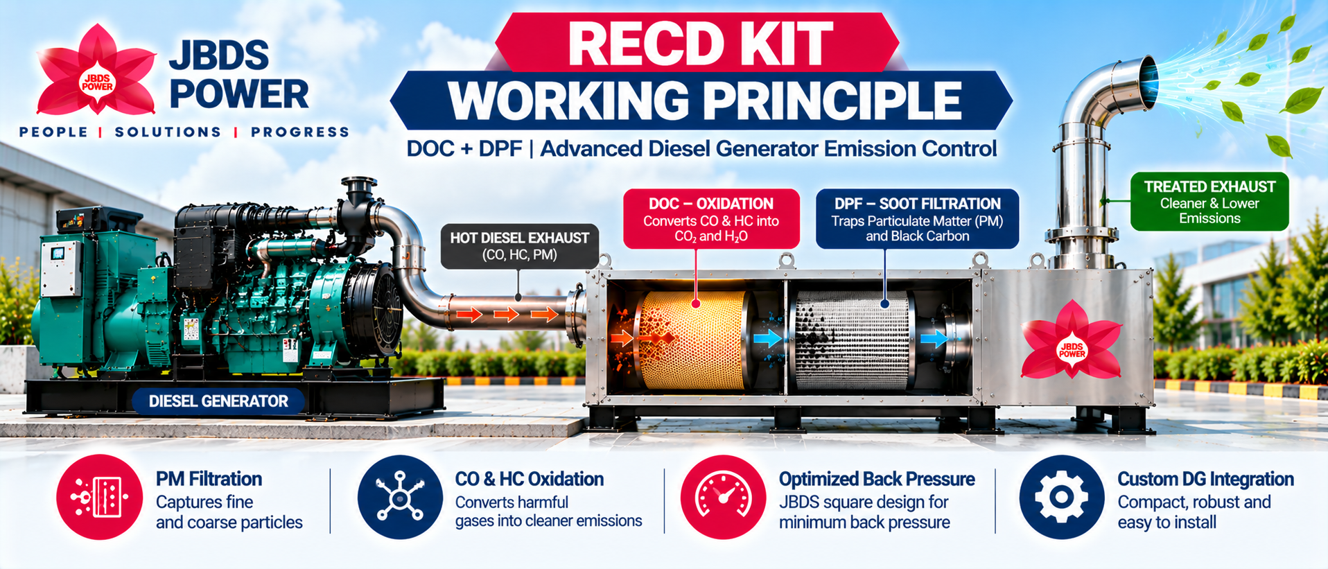
The JBDS Power RECD operates through multiple exhaust-treatment stages. Each stage performs a different function in reducing pollutants.
Stage 1: Untreated Exhaust Leaves the Diesel Engine
During diesel-engine operation, fuel and air burn inside the engine cylinders.
The resulting exhaust contains a mixture of gases, water vapour, soot particles and other combustion products.
This untreated exhaust passes through the engine exhaust manifold and exhaust piping toward the RECD inlet.
Several operating parameters affect the treatment process:
Exhaust gas temperature
Exhaust flow rate
Engine load
Particulate concentration
Exhaust pressure
Engine maintenance condition
An RECD must be selected according to these exhaust characteristics and the permissible exhaust-system back pressure specified by the engine manufacturer.
Stage 2: Exhaust Enters the RECD Housing
The exhaust enters the specially engineered RECD housing through the inlet connection.
The housing directs the exhaust through the internal treatment components.
JBDS Power uses a compact, industrial square-body design developed to accommodate the treatment elements while managing exhaust flow and back pressure.
The actual internal arrangement must be engineered according to the generator capacity and the required treatment performance.
Stage 3: Diesel Oxidation Catalyst Treats CO and HC
The exhaust reaches the Diesel Oxidation Catalyst (DOC).
The DOC promotes chemical oxidation reactions that convert certain pollutants into less harmful exhaust constituents.
This process depends strongly on exhaust temperature and catalyst activity.
Stage 4: Diesel Particulate Filter Captures Soot
After catalytic treatment, the exhaust enters the Diesel Particulate Filter (DPF).
The filter traps a substantial portion of diesel soot and particulate matter while allowing the exhaust gases to continue through its porous structure.
Stage 5: Captured Soot Is Managed Through Regeneration
As soot accumulates, the filter requires a suitable soot-management or regeneration mechanism.
Where exhaust temperature and operating conditions are sufficient, some accumulated soot can be oxidized through passive regeneration.
The actual regeneration method depends on the design of the particular RECD.
Stage 6: Treated Exhaust Leaves the Device
After passing through the treatment stages, the filtered exhaust exits through the RECD outlet and is routed toward the final discharge stack.
The objective is to produce an exhaust stream containing lower concentrations of the targeted pollutants while maintaining acceptable generator operating conditions.
Diesel Oxidation Catalyst (DOC): Working Principle in Detail
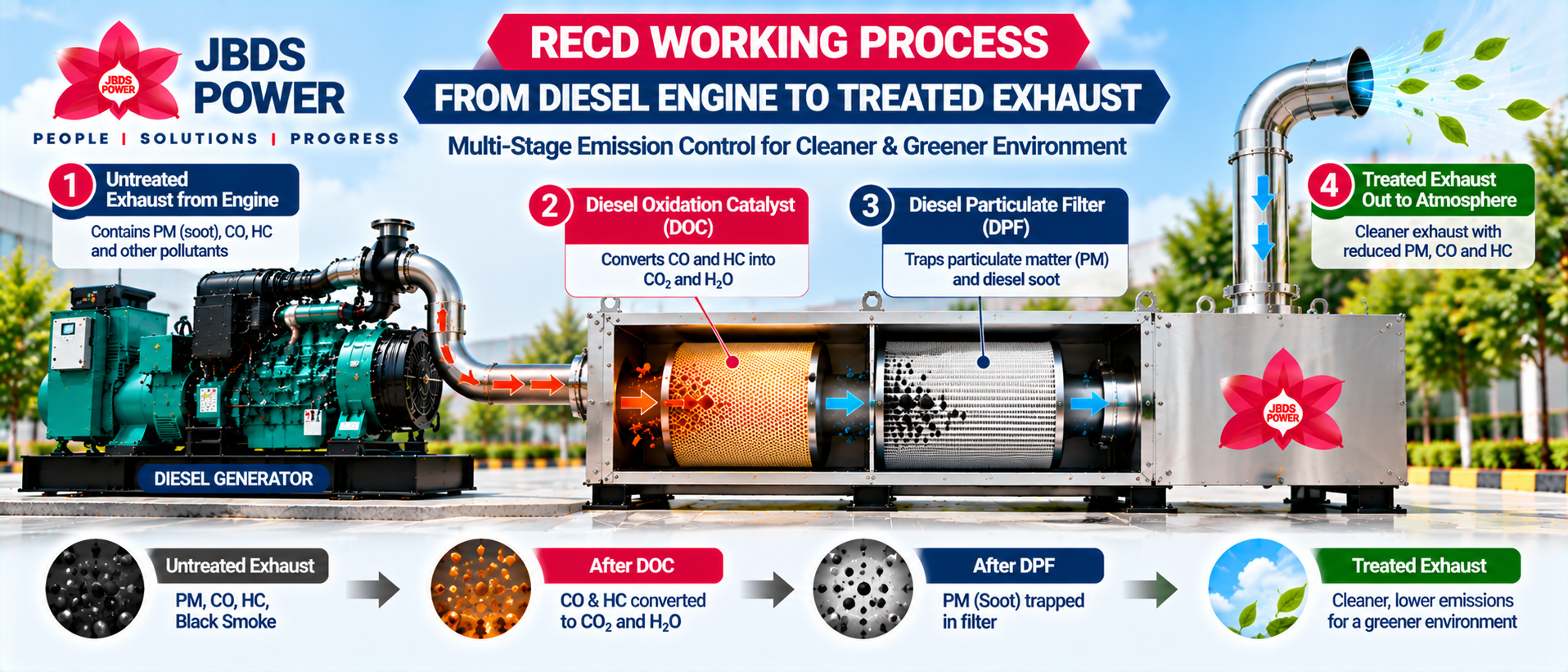
The Diesel Oxidation Catalyst (DOC) is an essential component of many diesel generator emission-control systems.
Its principal function is to accelerate oxidation reactions for certain pollutants without requiring the catalyst material itself to be consumed in the reaction.
DOC Internal Structure
A typical DOC contains a catalyst-coated substrate with numerous small flow channels.
The substrate may be manufactured from a suitable ceramic or metallic material and coated with catalytic materials.
As hot diesel exhaust passes through these channels, gaseous pollutants contact the catalytically active surface.
Main functions
Promote carbon monoxide oxidation.
Promote oxidation of unburnt hydrocarbons.
Help reduce some organic constituents associated with diesel particulates.
Support certain downstream particulate-filter regeneration strategies, depending on system design.
Chemical Reactions Inside the DOC
Carbon Monoxide Oxidation
Carbon monoxide reacts with oxygen to form carbon dioxide:
2CO + O₂ → 2CO₂
This reaction reduces the concentration of toxic carbon monoxide in the treated exhaust.
Hydrocarbon Oxidation
Hydrocarbons react with oxygen to form carbon dioxide and water vapour.
For a representative hydrocarbon, the reaction can be expressed as:
CₓHᵧ + (x + y/4)O₂ → xCO₂ + (y/2)H₂O
The actual hydrocarbons in diesel exhaust include a complex mixture of compounds.
Why Is Exhaust Temperature Important?
The DOC requires sufficient exhaust temperature to achieve useful catalytic conversion.
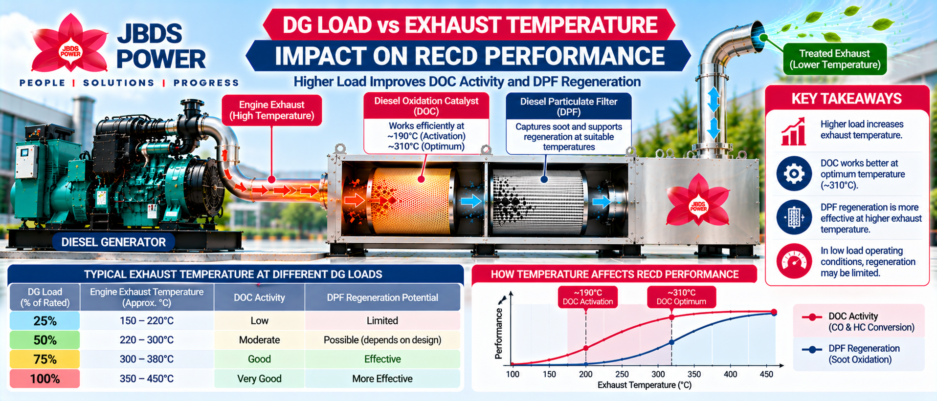
JBDS Power's published technical specifications describe DOC activation beginning around 190°C, with a stated optimum region around 310°C.
These temperatures should be treated as product-specific indicative operating conditions rather than universal activation temperatures for every catalyst.
At low exhaust temperatures, catalytic conversion may be limited.
As temperature increases into the designed operating window, oxidation reactions become more effective, provided the catalyst remains in suitable condition.
Factors Affecting DOC Efficiency
Exhaust temperature and flow rate
Catalyst formulation and condition
CO and HC concentrations
Oxygen availability
Exhaust residence time
Contamination or catalyst poisoning
Engine operating load
The DOC performance must be assessed through appropriate testing rather than assuming that all generators achieve identical conversion efficiency.
Diesel Particulate Filter (DPF): How Soot Filtration Works
The Diesel Particulate Filter (DPF) is the primary soot-capture component in a DOC + DPF emission-control system.
Its function is different from that of the DOC.
The DOC primarily promotes oxidation of gaseous pollutants, while the DPF physically captures particulate matter from the diesel exhaust.
DPF Internal Structure
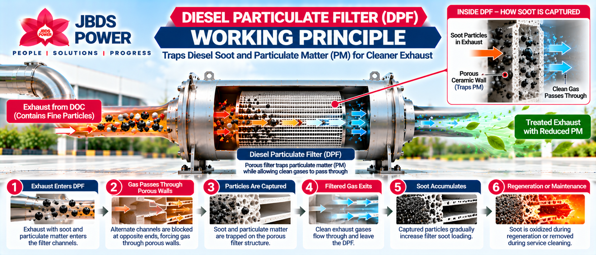
Many DPF systems use a porous wall-flow filter structure.
In a typical wall-flow arrangement, alternate channels are blocked at opposite ends.
This forces the exhaust gas to pass through porous channel walls before leaving the filter.
As exhaust travels through these walls, soot particles are captured on or within the filter structure.
Step-by-Step DPF Filtration
Step 1 – Exhaust Enters the DPF: Exhaust containing soot enters the filter channels.
Step 2 – Gas Passes Through Porous Walls: The channel arrangement directs exhaust through the filter material.
Step 3 – Particles Are Captured: Soot and other particulate matter are retained by the filter.
Step 4 – Filtered Gas Exits: Gas flows into the outlet channels and leaves the DPF.
Step 5 – Soot Accumulates: Captured particles gradually increase the filter's soot loading.
Step 6 – Regeneration or Maintenance: Accumulated soot must be managed to prevent excessive restriction.
Does a DPF Capture Visible Black Smoke?
Yes. A properly functioning DPF can capture a substantial portion of the soot responsible for visible black smoke.
However, particulate emissions also include very small particles that may not be individually visible.
The effectiveness of a DPF should therefore be evaluated through emission testing, not merely by inspecting the exhaust colour.
DPF Regeneration: How an RECD Manages Collected Carbon
Over time, the DPF collects soot from the exhaust stream.
If soot continues to accumulate without being removed or oxidized, exhaust restriction increases.
This is why DPF regeneration is a critical part of particulate-filter operation.
Regeneration is the controlled oxidation of accumulated combustible soot.
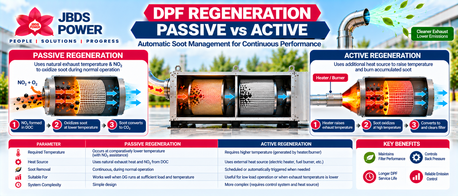
1. Passive Regeneration
Passive regeneration occurs when exhaust temperature and chemical conditions support soot oxidation during normal engine operation.
In systems designed for this process, nitrogen dioxide generated through upstream oxidation chemistry may help promote soot oxidation at temperatures lower than those required for direct oxygen-based soot burning.
A simplified carbon-oxidation reaction is:
C + O₂ → CO₂
An example of nitrogen-dioxide-assisted soot oxidation is:
C + 2NO₂ → CO₂ + 2NO
Actual reaction pathways are more complex and depend on catalyst formulation and operating conditions.
2. Active Regeneration
Some DPF systems use an active regeneration strategy to increase temperature or otherwise create suitable soot-oxidation conditions.
Active regeneration can involve dedicated heaters, burners or other engineered arrangements.
Not every retrofit RECD includes an active regeneration system. Whether this method is available depends on the exact product design.
3. Passive Regeneration Limitations
If a DG operates for long periods at low load, its exhaust temperature may remain too low for effective soot oxidation.
This can result in progressive soot accumulation.
For that reason, generator load patterns and exhaust temperature are important when selecting a DOC + DPF system.
4. Soot vs Ash
Soot is largely combustible carbonaceous material and may be removed through successful regeneration.
Ash consists of noncombustible residue from sources such as lubricating-oil additives and engine wear.
Ash is not removed by normal soot regeneration. It generally requires an appropriate service-cleaning process.
JBDS Power identifies carbon self-cleaning as a feature of its RECD technology, but site-specific regeneration performance must still be evaluated according to exhaust conditions and the installed product configuration.
Exhaust Back Pressure: Why RECD Design Matters
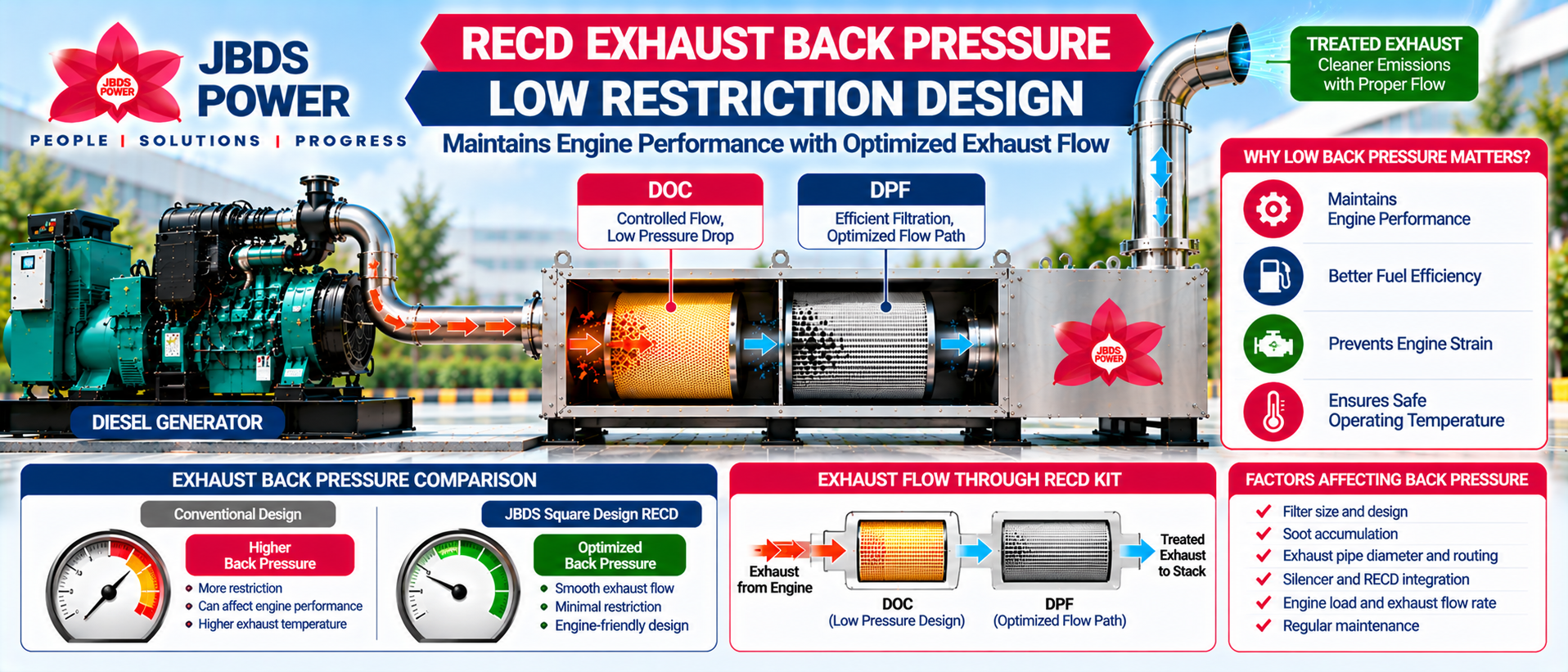
Installing an exhaust-treatment device introduces resistance to exhaust flow.
This resistance is commonly described through exhaust back pressure.
Excessive back pressure can affect diesel-engine performance and should be avoided.
What Causes Back Pressure?
Back pressure may be influenced by:
Filter resistance
Soot accumulation
Exhaust-pipe diameter
Pipe bends and routing
RECD internal flow distribution
Exhaust silencer configuration
Exhaust volume and velocity
Filter condition
Why Does It Matter?
Excessive exhaust restriction can increase the work required to expel exhaust gases from an engine.
Depending on the engine and operating conditions, this can contribute to performance problems, higher exhaust temperatures or other operating concerns.
JBDS Power Low Back Pressure Design
JBDS Power's square-body RECD design is engineered to support efficient exhaust distribution and reduced flow restriction.
The objective is to maintain exhaust pressure within permissible engine limits while providing effective pollutant treatment.
An RECD should never be considered a zero-back-pressure device. The total installed exhaust-system back pressure should be checked under appropriate operating conditions and compared with the engine manufacturer's permitted limit.
RECD Temperature, DG Load and Filtration Performance
The working efficiency of an RECD depends on how the diesel generator operates.
A generator running at a low load may produce significantly different exhaust conditions from one operating near its normal working load.
Relationship Between DG Load and Exhaust Temperature
In general, increasing engine load can increase exhaust temperature, although actual results depend on engine design and operating conditions.
Low exhaust temperatures can reduce DOC activity and limit passive soot regeneration.
Higher temperatures within the designed operating range can improve catalytic conversion and assist regeneration.
However, excessive exhaust temperatures can damage catalyst or filter components.
Operating Conditions to Monitor
Parameter | Importance |
|---|---|
DG load | Influences exhaust temperature and flow |
Exhaust inlet temperature | Helps determine DOC and DPF operating conditions |
Exhaust outlet temperature | Useful for understanding thermal behaviour |
Differential pressure | Can indicate increasing filter restriction |
Engine back pressure | Must remain within engine limits |
DG running hours | Helps plan inspection and maintenance |
Visible exhaust smoke | Can indicate combustion or filtration problems |
Maintenance history | Helps identify deterioration and recurring issues |
For reliable performance, the RECD should be selected with the generator's actual operating pattern in mind.
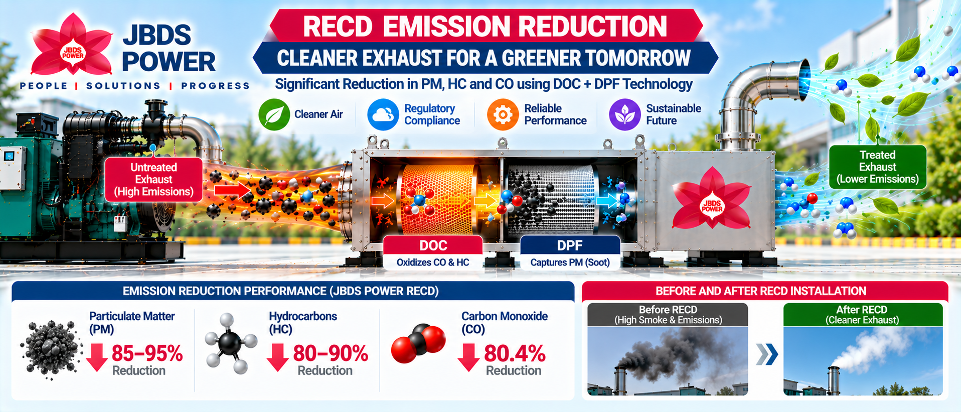
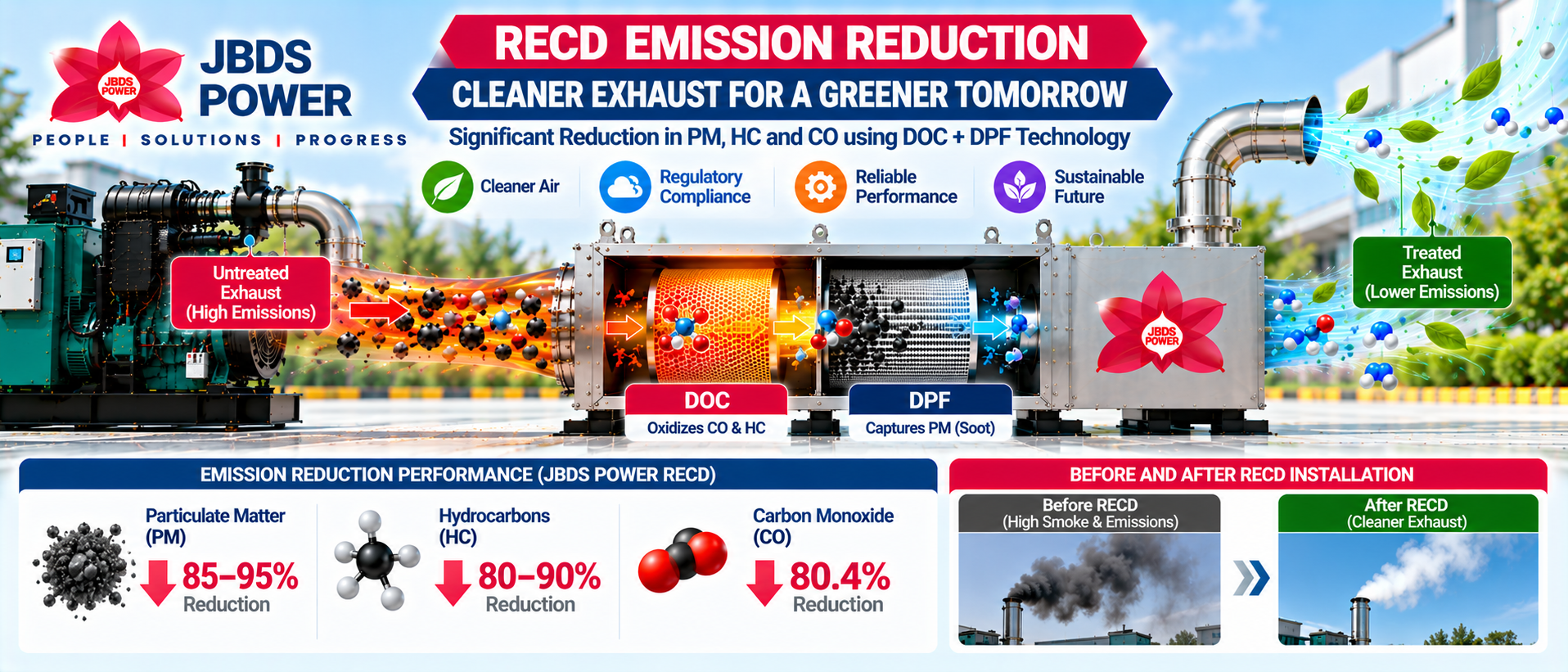
RECD Emission Reduction Performance: PM, CO and HC
JBDS Power publishes emission-reduction specifications for its RECD technology.
The stated performance figures include:
Emission parameter | JBDS Power published specification |
|---|---|
Particulate Matter (PM) | Up to 85–95% reduction |
Hydrocarbons (HC) | Up to 80–90% reduction |
Carbon Monoxide (CO) | Up to 80.4% reduction |
Core technology | DOC + DPF |
DOC operating region | Activation around 190°C; optimum around 310°C |
Design | Compact square-body RECD |
These figures represent the company's published product specifications and should not be interpreted as guaranteed results for every installation.
Actual measured reductions depend on:
Engine configuration
Operating load
Exhaust temperature
Filter and catalyst condition
Installation design
Maintenance
Applicable testing conditions
For a specific installation, the relevant type-approval documentation, technical specifications and commissioning results should be reviewed.
RECD Kit Installation: Exhaust Flow and System Integration
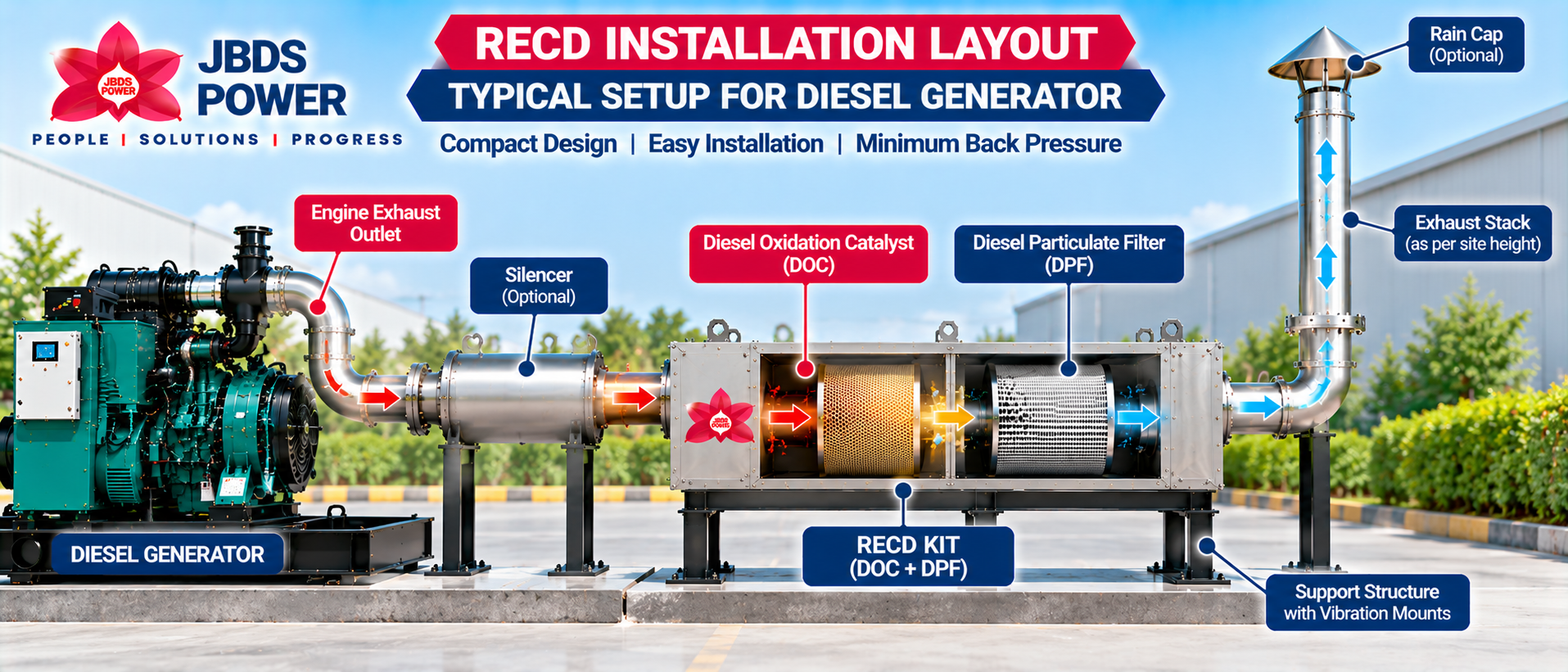
A Retrofit Emission Control Device is normally integrated into the diesel generator exhaust system.
Proper installation is essential for exhaust treatment and safe engine operation.
Typical Installation Arrangement
DG Engine → Exhaust Pipe → RECD Inlet → DOC + DPF → RECD Outlet → Exhaust Stack
The actual silencer and RECD arrangement depends on the selected system and approved installation design.
Installation Engineering Requirements
DG Technical Assessment
Record the generator capacity, engine model, exhaust parameters and permissible back pressure.
Site Survey
Review available space, maintenance access, exhaust routing and mounting arrangement.
RECD Selection
Select a correctly sized and technically suitable RECD configuration.
Mechanical Installation
Provide correctly designed mounting supports, exhaust connections and thermal considerations.
Exhaust System Integration
Ensure that pipe sizing, exhaust routing and any silencer arrangement are compatible with the installed system.
Testing and Commissioning
Check exhaust leakage, temperature, back pressure and other operating conditions.
Handover and Maintenance Instructions
Provide operating instructions and recommended inspection and servicing requirements.
JBDS Power supports customized engineering, installation, testing and commissioning for industrial RECD projects.
RECD Maintenance, Inspection and Troubleshooting
Although an RECD is installed outside the engine, proper maintenance remains important.
The DOC, DPF, housing and exhaust connections should be inspected according to manufacturer guidance and actual operating conditions.
Recommended Inspection Areas
Exhaust inlet and outlet connections
Exhaust leakage
Catalyst and filter condition
Mounting brackets
Thermal insulation, where provided
Differential pressure or back-pressure readings
Signs of soot accumulation
Unusual engine or exhaust behaviour
Regeneration performance
Service history
Common Problems and Possible Causes
Observation | Possible causes |
|---|---|
Increasing exhaust back pressure | Soot loading, ash accumulation or exhaust restriction |
Persistent visible smoke | Engine combustion issue, filter damage or bypass/leakage |
Poor soot regeneration | Low exhaust temperature or unsuitable load pattern |
Reduced catalytic performance | Low temperature, contamination or catalyst deterioration |
Exhaust leakage | Damaged gasket, joint or connection |
Unusual temperature | Engine operating issue, regeneration condition or exhaust restriction |
These are diagnostic possibilities rather than definitive causes.
Any cleaning or servicing must follow the product-specific instructions. Removing a DPF or using unsuitable cleaning procedures can damage the filter or release collected hazardous material.
How Is an RECD Different from a DFK or Conventional Silencer?
Three different technologies are sometimes confused: RECD, Dual Fuel Kit and DG exhaust silencer.
Their functions are not the same.
System | Main function | Installation area |
|---|---|---|
RECD Kit | Reduce targeted exhaust pollutants | DG exhaust line |
Dual Fuel Kit (DFK) | Substitute part of diesel fuel with natural gas | Fuel / intake control system |
Exhaust Silencer | Reduce exhaust noise | DG exhaust line |
A Dual Fuel Kit influences the fuel used during combustion.
An RECD Kit treats the exhaust after combustion.
A Silencer primarily controls exhaust noise and should not be treated as a substitute for emission after-treatment.
JBDS Power provides both RECD and Dual Fuel solutions for suitable diesel generator applications.
RECD Certification, CPCB Guidelines and ICAT Testing
RECD compliance requirements depend on generator capacity, location, age, application and current regulatory directions.
The Central Pollution Control Board (CPCB) has published procedures for emission-compliance testing of retrofit emission control devices for applicable diesel power generating engines.
Type-approval and emission testing help establish whether a particular RECD model meets the requirements of the relevant test procedure.
JBDS Power publishes ICAT testing and certification information for its RECD solutions.
What Should a Buyer Verify?
Applicable DG capacity and engine category
Valid RECD approval or certification documentation
Match between the installed product and approved configuration
Required pollutant-reduction performance
Engine back-pressure requirements
Site-specific regulatory conditions
Commissioning and maintenance documentation
Important: An RECD installation does not automatically guarantee permission to operate a DG under every pollution-control restriction. Applicable CPCB, State Pollution Control Board and CAQM directions should be checked for the location and date of operation.
Applications of JBDS Power RECD Kits
RECD technology is relevant to existing diesel generators used in a range of sectors.
Typical applications include:
Industrial Manufacturing Plants
Government Institutions
Defence Establishments
Hospitals and Healthcare Facilities
Commercial Buildings
Data Centers
Educational Institutions
Warehouses and Logistics Parks
Infrastructure Projects
Oil and Gas Facilities
Construction Projects
Industrial Backup Power Systems
JBDS Power reports RECD installation experience across government institutions, Indian Army, ICAR, HAL, IOCL, hospitals, manufacturing and other sectors.
A final RECD recommendation should always be based on generator specifications and actual site requirements.
Why Choose JBDS Power for RECD Kit Engineering?
An effective RECD installation requires a combination of emissions engineering, mechanical design, product selection and installation expertise.
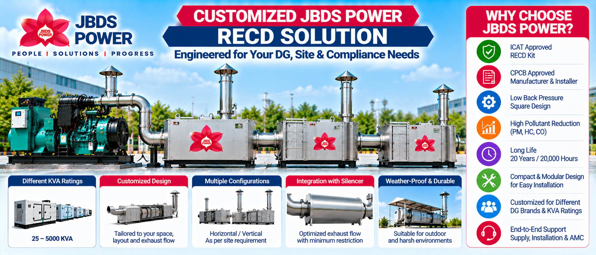
JBDS Power provides customized Retrofit Emission Control Device solutions for industrial diesel generator applications.
JBDS Power Capabilities
DOC + DPF-Based Emission Control Technology
ICAT-Tested RECD Solutions
Engine and DG-Specific Product Selection
Optimized Square-Body RECD Design
Low Back Pressure Engineering
Industrial Fabrication and Manufacturing
Exhaust System Integration
Site Survey and Application Engineering
Installation and Commissioning
Technical Service and Maintenance Support
PAN-India Project Support
The objective is to achieve effective exhaust-treatment performance while maintaining the generator's operating requirements.
Frequently Asked Questions About the RECD Working Principle
1. How does an RECD Kit work in a diesel generator?
An RECD treats exhaust produced by an operating diesel generator. The DOC stage oxidizes certain gaseous pollutants, while the DPF captures soot and particulate matter before treated exhaust leaves the system.
2. What is the role of DOC in an RECD?
The Diesel Oxidation Catalyst promotes oxidation of carbon monoxide and hydrocarbons under suitable exhaust-temperature conditions.
3. What is the role of DPF in an RECD?
The Diesel Particulate Filter captures diesel soot and other particulate matter by passing exhaust through a suitable filtration structure.
4. What is DPF regeneration?
DPF regeneration is the oxidation of accumulated combustible soot. Depending on the system, it may take place passively under suitable conditions or through a dedicated active regeneration mechanism.
5. Does an RECD eliminate 100% of diesel pollution?
No. RECD performance varies according to pollutant type, technology, operating conditions and the specific product configuration.
6. Can an RECD reduce black smoke?
Yes. A suitable DPF can capture much of the soot that contributes to visible black smoke.
7. Does an RECD increase back pressure?
Every exhaust after-treatment device introduces some resistance. A properly designed RECD installation must maintain total engine exhaust back pressure within the permissible limit.
8. At what temperature does the DOC work?
The working temperature depends on catalyst design. JBDS Power publishes an indicative activation region around 190°C and an optimum operating region around 310°C for its technology.
9. Is an RECD the same as a catalytic converter?
An RECD may incorporate a catalytic converter as one treatment stage, but a DOC + DPF RECD also includes particulate filtration and associated exhaust-system engineering.
10. Is JBDS Power an RECD Kit Manufacturer in India?
JBDS Power offers engineered RECD Kits for diesel generators, including product selection, installation, commissioning and technical support.
Contact JBDS Power for RECD Kits and Technical Consultation
If you want to reduce emissions from your existing diesel generator, JBDS Power can help evaluate your DG installation and recommend a suitable RECD solution.
For technical assessment, provide:
DG capacity in KVA
Engine make and model
Generator manufacturing year
Average operating load
Daily running hours
Existing exhaust arrangement
Installation location
Site photographs or layout
Applicable compliance requirements
JBDS POWER GROUP
Phone: +91 7290054361
Email: digital@jbdspower.com
Email: info@jbdspower.com
Head Office: Plot No. 302, Sector 7, IMT Manesar, Gurgaon, Haryana – 122052
Explore our JBDS Power RECD Kit solutions or Contact JBDS Power for your application.
JBDS Power – Engineering Cleaner Diesel Generator Operations.